dienelectrics@gmail.com
 0909186879 dienelectrics@gmail.com

Unless explicitly specified otherwise, the following technical specifications are valid for all components of the SINAMICS S120 booksize drive system.
Note:
When engineering the complete SINAMICS S120 drive, the system data of the associated Control Units, supplementary system components, DC link components and Sensor Modules must be taken into consideration.
|
Electrical specifications |
|||
|
Line voltage |
380 ... 480 V 3 AC ±10 % (-15 % <1 min) |
||
|
Line system configurations |
Grounded TN/TT systems and non-grounded IT systems |
||
|
Line frequency |
47 ... 63 Hz |
||
|
Electronics power supply |
24 V DC -15 %/+20 %1), safety extra low-voltage (PELV/SELV) |
||
|
Short-circuit current rating (SCCR) (Short Circuit Current Rating) |
1.1 ... 447 kW: 65 kA |
||
|
Electromagnetic compatibility According to EN 61800‑3 |
Second environment, Category C2/C3 For further information, see section Configuration notes |
||
|
Overvoltage category According to IEC/EN 61800‑5‑1 |
III |
||
|
Mechanical specifications |
|||
|
Degree of protection |
|
||
|
IP20 |
||
|
Open type |
||
|
Protection class |
|
||
|
I |
||
|
Safety extra low-voltage PELV/SELV |
||
|
Ambient conditions |
|||
|
|
Storage |
Transport |
Operation |
|
In product packaging |
In transport packaging |
|
|
|
Climatic environmental conditions |
Class 1K4 |
Class 2K4 |
Class 3K3 3) Relative humidity 5 ... 95 % |
|
Environmental class/harmful chemical substances |
Class 1C2 |
Class 2C2 |
Class 3C2 |
|
Organic/biological influences |
Class 1B1 |
Class 2B1 |
Class 3B1 |
|
Pollution degree 2) acc. to IEC/EN 61800‑5‑1 |
2 |
||
|
Installation altitude |
|
||
|
Without derating |
||
|
|
||
|
|
||
|
and additionally:
|
||
|
|
||
|
Mechanical strength |
|||
|
|
Storage |
Transport |
Operation |
|
In product packaging |
In transport packaging |
|
|
|
Vibratory load |
Class 1M2 |
Class 2M3 |
Class 3M1 |
|
Shock load |
Class 1M2 |
Class 2M3 |
Class 3M1 |
|
Certificates |
|||
|
Declarations of conformity |
CE (Low Voltage, EMC and Machinery Directive) |
||
|
Certificates of suitability |
cULus |
||
1) When using a motor holding brake, restricted voltage tolerances (24 V ±10 %) might need to be taken into account.
2) The components must be protected against conductive pollution, e.g. by installing them in a control cabinet with degree of protection IP54 according to IEC 60529 or NEMA 12. If conductive pollution can be excluded at the installation site, a lower degree of cabinet protection is permissible.
3) Better than 3K3 through increased ruggedness regarding the temperature range and humidity. Oil mist, salt mist, ice formation, condensation, dripping water, spraying water, splashing water and water jets are not permitted.
4) Also carefully observe the permissible temperatures for the Control Unit and operator panel.
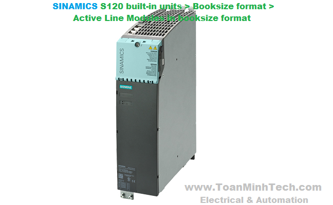
Active Line Modules are self-commutated infeed/regenerative feedback units (with IGBTs in the infeed and regenerative feedback directions) that generate a controlled DC link voltage. This means that the connected Motor Modules are decoupled from the line voltage. Line voltage fluctuations within the permissible supply tolerances have no effect on the motor voltage. Active Line Modules are designed for connection to grounded star (TN, TT) and non-grounded symmetrical (IT) supply systems.
The DC link is pre-charged via integrated precharging resistors.
In order to operate an Active Line Module, an associated Active Interface Module is required.
The Active Line Modules in booksize format feature the following connections and interfaces as standard:
- 1 power connection via screw-type terminals
The status of the Active Line Modules is indicated via two multi-color LEDs.
For the Active Line Module with a width of 100 mm (3.94 in), the shield of the power connection cable can be connected to the integrated shield connection plate by means of a shield connection terminal or hose clip, e.g. Weidmüller type KLBÜ CO 4. The shield connection terminal must not be used as a strain relief mechanism. Shield connection sets are available for the 150 mm (5.91 in), 200 mm (7.87 in) and 300 mm (11.81 in) wide Active Line Modules.
The signal cable shield can be connected to the Active Line Module by means of a shield connection clamp, e.g. Weidmüller type KLBÜ 3-8 SC.
The scope of supply of the Active Line Modules includes:
The Active Line Module receives its control information via DRIVE‑CLiQ from:
- CU320‑2 Control Unit
Connection example of Active Line Module in booksize format
|
|
Active Line Module in booksize format 6SL3130-7TE... |
|---|---|
|
Line voltage (up to 2000 m (6562 ft) above sea level) |
380 ... 480 V 3 AC ±10 % (in operation -15 % <1 min) |
|
Line frequency |
47 ... 63 Hz |
|
SCCR (short-circuit current rating) |
65 kA in conjunction with the recommended Class J fuse, or circuit breaker according to UL489 / CSA 22.2 No. 5-02 see recommended line-side components |
|
Line power factor |
|
|
|
|
1 (factory setting), can be altered by inputting a reactive current setpoint |
|
1 (factory setting) |
|
|
|
>0.96 |
|
0.65 ... 0.9 |
|
Overvoltage category to EN 60664‑1 |
Class III |
|
DC link voltage Vd |
In Active Mode, the DC link voltage is regulated and can be adjusted as a voltage decoupled from the line voltage. In Smart Mode, the DC link voltage is kept in proportion to the line voltage at the mean rectified line voltage value. Factory setting for DC link voltage: 380 ... 400 V 3 AC: 600 V (Active Mode) 400 ... 415 V 3 AC: 625 V (Active Mode) 416 ... 480 V 3 AC: 1.35 × line voltage (Smart Mode) 1) |
|
Electronics power supply |
24 V DC -15 %/+20 % |
|
Radio interference suppression |
|
|
Category C3 to EN 61800‑3 up to 350 m (1148 ft) total cable length |
|
Category C2 according to EN 61800-3 up to 350 m (1148 ft) total cable length |
|
Type of cooling |
Internal air cooling (power units with increased air cooling by built-in fan) |
|
Permissible ambient and coolant temperature (air) during operation for line-side components, Line Modules and Motor Modules |
0 ... 40 °C (32 ... 104 °F) without derating, |
|
Installation altitude |
Up to 1000 m (3281 ft) above sea level without derating, |
|
Declarations of conformity |
CE (Low Voltage and EMC Directives) |
|
Certificate of suitability |
cULus |
1) Active Mode can also be selected if the connected motors are suitable for > 650 V DC.
|
Line voltage 380 ... 480 V 3 AC |
Active Line Module in booksize format |
|||||
|---|---|---|---|---|---|---|
|
Internal air cooling |
6SL3130-7TE21-6AA4 |
6SL3130-7TE23-6AA3 |
6SL3130-7TE25-5AA3 |
6SL3130-7TE28-0AA3 |
6SL3130-7TE31-2AA3 |
|
|
Infeed/regenerative feedback power |
|
|
|
|
|
|
|
|
|
|
|
|
|
|
kW |
16 |
36 |
55 |
80 |
120 |
|
(hp) |
(18) |
(40) |
(60) |
(100) |
(150) |
|
kW |
21 |
47 |
71 |
106 |
145 |
|
kW |
35 |
70 |
91 (110 1)) |
131 |
175 |
|
DC link current |
|
|
|
|
|
|
|
A |
27 |
60 |
92 |
134 |
200 |
|
A |
35 |
79 |
121 |
176 |
244 |
|
A |
59 |
117 |
152 (176 1)) |
218 |
292 |
|
Input current |
|
|
|
|
|
|
|
A |
26/25/21 |
58/55/46 |
88/84/70 |
128/122/102 |
192/182/152 |
|
A |
32 |
71 |
108 |
161 |
220 |
|
A |
54 |
107 |
139 (168 1)) |
200 |
267 |
|
Current requirement 24 V DC electronics power supply, max. |
A |
1.1 |
1.5 |
1.9 |
2 |
2.5 |
|
Current carrying capacity |
|
|
|
|
|
|
|
A |
20 |
20 |
20 |
20 |
20 |
|
A |
100 |
200 |
200 |
200 |
200 |
|
DC link capacitance |
|
|
|
|
|
|
|
μF |
710 |
1410 |
1880 |
2820 |
3995 |
|
μF |
20000 |
20000 |
20000 |
20000 |
20000 |
|
Power loss 2) |
kW |
0.28 |
0.67 |
0.95 |
1.38 |
2.24 |
|
Cooling air requirement |
m3/s (ft3/s) |
0.016 (0.57) |
0.031 (1.09) |
0.044 (0.155) |
0.144 (5.09) |
0.144 (5.09) |
|
Sound pressure level LpA (1 m) |
dB |
<60 |
<65 |
<60 |
<73 |
<73 |
|
Line connection U1, V1, W1 |
|
Screw-type terminals (X1) |
M6 screw studs (X1) |
M8 screw studs (X1) |
M8 screw studs (X1) |
M8 screw studs (X1) |
|
mm2 |
2.5 ... 10 |
2.5 ... 50 |
2.5 ... 95, 2 × 35 |
2.5 ... 120, 2 × 50 |
2.5 ... 120, 2 × 50 |
|
Shield connection |
|
Integrated in the connector |
See Accessories |
See Accessories |
See Accessories |
See Accessories |
|
PE connection |
|
M5 screw |
M6 screw |
M6 screw |
M8 screw |
M8 screw |
|
Cable length, max. Total of all motor cables and DC link |
|
|
|
|
|
|
|
m (ft) |
630 (2067) 3) |
630 (2067) 3) |
1000 (3281) |
1000 (3281) |
1000 (3281) |
|
m (ft) |
850 (2789) |
850 (2789) |
1500 (4922) |
1500 (4922) |
1500 (4922) |
|
Degree of protection |
|
IP20 |
IP20 |
IP20 |
IP20 |
IP20 |
|
Dimensions |
|
|
|
|
|
|
|
mm (in) |
100 (3.94) |
150 (5.91) |
200 (7.87) |
300 (11.81) |
300 (11.81) |
|
mm (in) |
380 (14.96) |
380 (14.96) |
380 (14.96) |
380 (14.96) |
380 (14.96) |
|
mm (in) |
– |
– |
– |
629 (24.76) |
629 (24.76) |
|
mm (in) |
270 (10.63) |
270 (10.63) |
270 (10.63) |
270 (10.63) |
270 (10.63) |
|
Weight, approx. |
kg (lb) |
7 (15.4) |
10 (22.0) |
17 (37.5) |
23 (50.7) |
23 (50.7) |
1) Higher peak output is possible in combination with the Active Interface Module 6SL3100-0BE25-5AB0 (for operating cycle constraints, see SINAMICS S120 Manual).
2) Power loss of Active Line Module at rated output including losses of 24 V DC electronics power supply.
3) Max. cable lengths in combination with Active Interface Module and Basic Line Filter (Category C3 according to EN 61800‑3).
4) The fan is supplied together with the Active Line Module and must be installed before the Active Line Module is commissioned.
5) Nominal HP ratings are provided for ease of assigning components only. The Line Module outputs are dependent on the Motor Module loading and are to be dimensioned accordingly.

Duty cycle with previous load

S6 duty cycle with previous load

S6 duty cycle with previous load
55 kW Active Line Module only:

Peak power load duty cycle with previous load

Output power as a function of ambient temperature
Installation altitude
- >1000 ... 4000 m (3281 ... 13124 ft) above sea level